Hands-on product engineering and manufacturing experience.
Representative experience
Products, tooling and automation
Examples of product development, factory equipment, toolmaking and manufactured parts.
Career experience
Our team’s combined project experience
Tooling components and deliverables taken through completion.
Tooling programmes managed across global supply chains.
Manufacturing volumes supported from launch into production.
Figures reflect the cumulative career experience of the people behind Paniani, across prior roles and client projects.
Product case studies
PuppyDock, CableX and MochaMelts

Pet products / Mechanical design
PuppyDock pool ramp
PuppyDock began after its founders’ puppy fell into a pool and could swim but could not get out. The product provides an adjustable route between the water and the pool edge.
Its polyethylene body and rubber grip pads are designed for pool use, with blue and yellow surfaces and articulated sections that adjust to the installation.
Visit PuppyDock ↗Ramp geometry and grip
The design combines connected moulded sections, grip pads and pool-edge attachments. Adjustment, footing and resistance to the pool environment are central product requirements.
Pool installation
The ramp attaches using straps or bolts, depending on the installation and dog’s weight. It assists pool access but does not replace supervision.
Product specifications and use guide ↗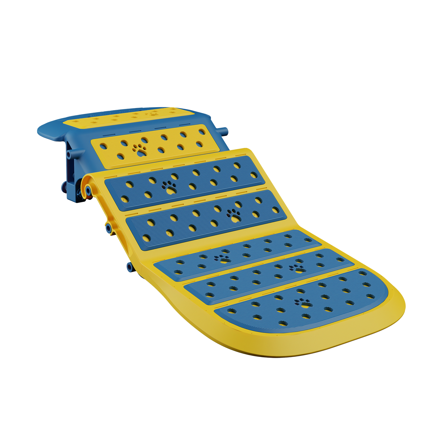
Charging products / Electro-mechanical design
CableX retractable wall charger
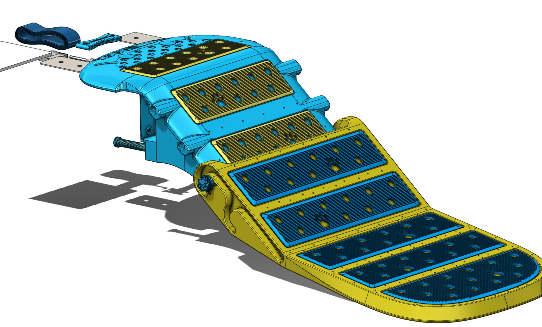
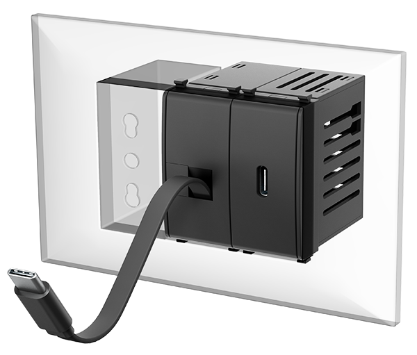
CableX integrates a charger and retractable cable into a wall installation. Users pull out the length they need, then return the cable into the unit when charging is finished.
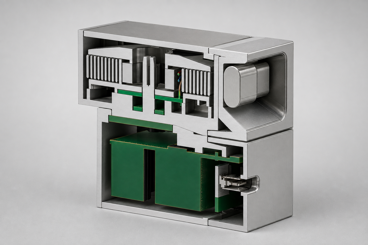
The system separates the Power Delivery electronics from the replaceable Tri-Lock cable module. A worn cable module can be replaced without replacing the complete installation.
Visit CableX ↗Charging and cable management
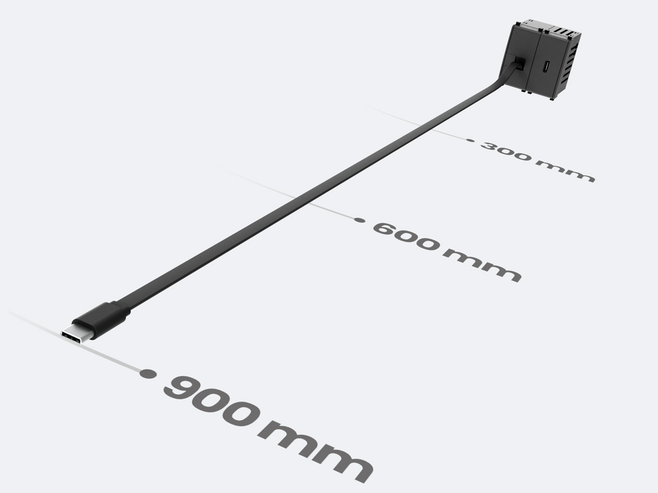
The published specification is up to 30W with one cable. Power is shared when two devices are connected. The retractable cable stops at 300, 600 and 900 mm.
Modular installation
The product combines the charging module, cable mechanism and faceplate interface in a compact enclosure. CableX lists compatibility with 14 faceplate models and three finish options.

Food products / Production development
MochaMelts espresso-filled chocolate
MochaMelts combines a thin dark-chocolate shell with a liquid espresso centre. Development has involved working prototypes, mould design and trials of shell thickness and liquid filling.
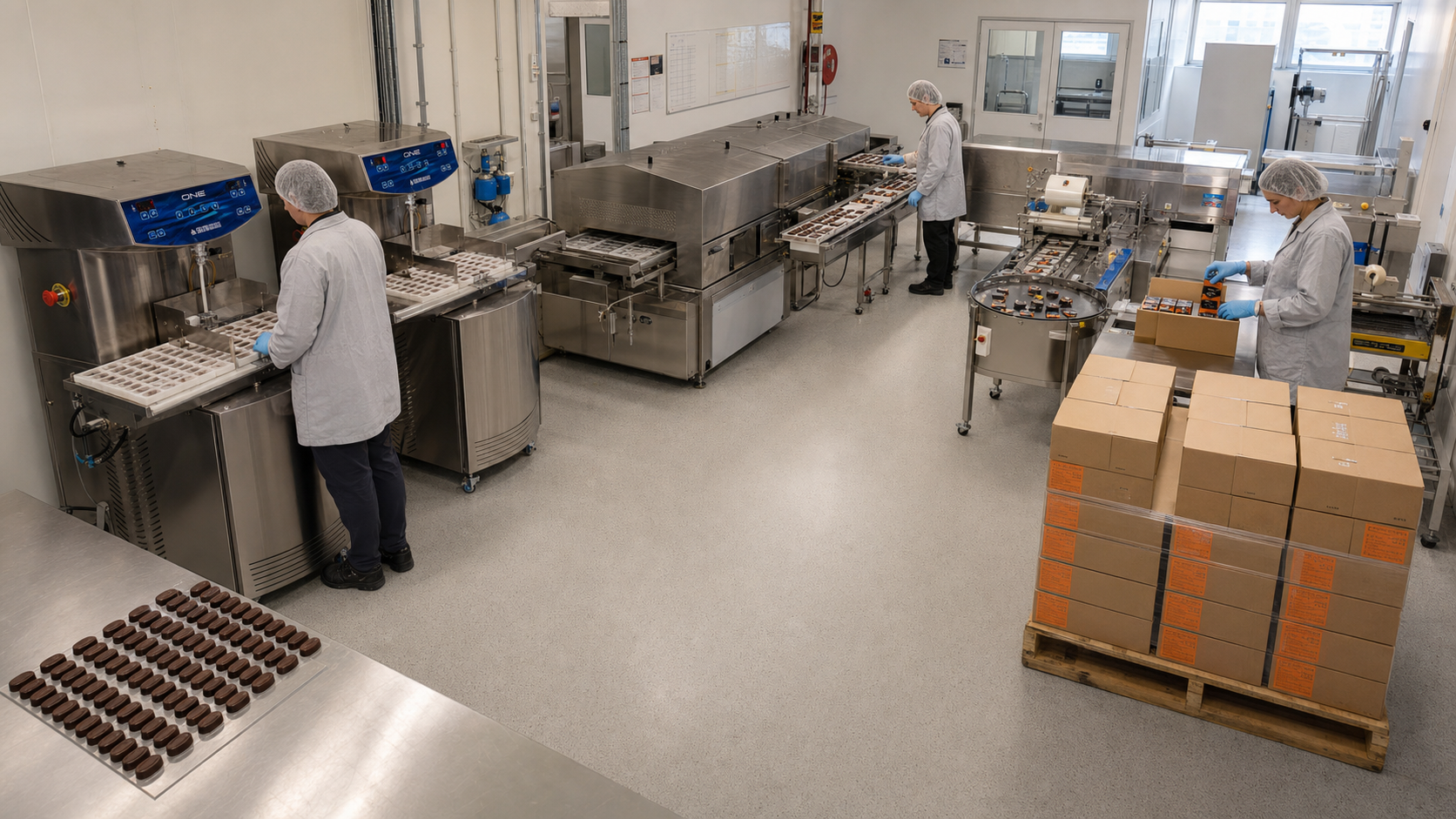
The next stage is production development: a compact line covering tempering, moulding, filling, sealing, wrapping and packing. The brand is preparing for an Australian launch in mid-2027.
Visit MochaMelts ↗Prototype moulding and filling
The product needs a shell that releases from the mould, holds the liquid centre and survives handling. Prototype work provides a basis for refining these steps before production equipment is finalised.
Production line and automation
Equipment planning connects the moulding and filling stages with wrapping and packing. The layout shown is a proposed production line, not an operating factory.
Prototype and production development story ↗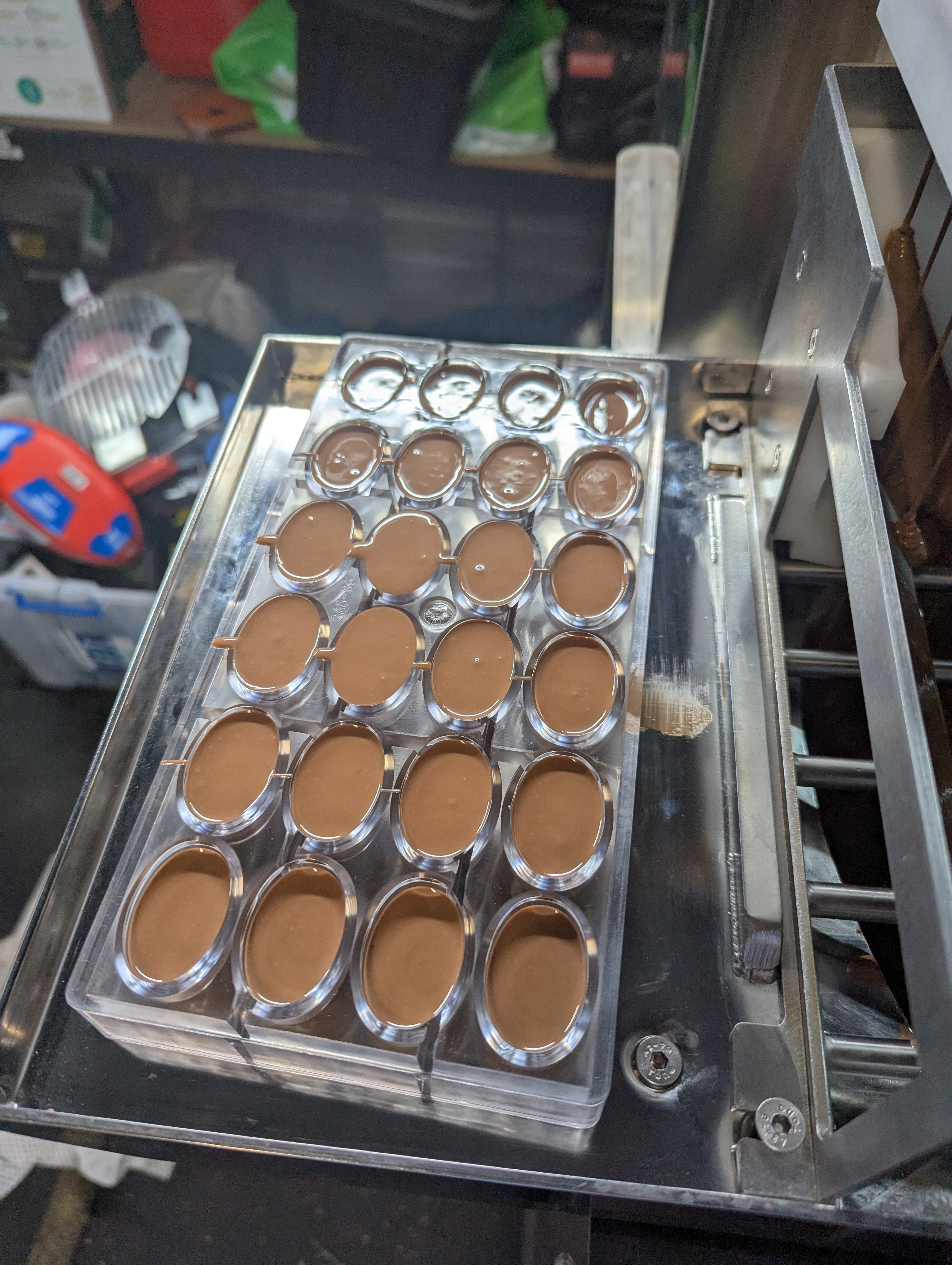
Factory automation
Syringe handling and robotic food packaging
Two examples from Tony’s project experience in pharmaceutical production and food packaging, covering mechanical design and equipment integration.
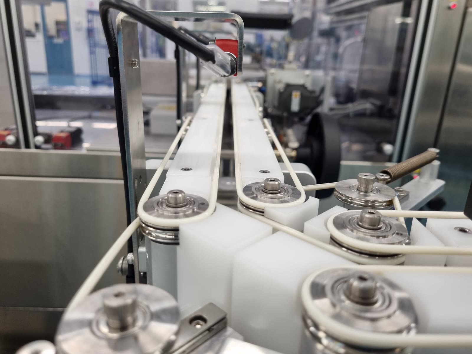
Pharmaceutical production
Syringe handling conveyor
A conveyor linking existing filling and packaging equipment. Eight independently controlled sections manage syringe flow and grouping before blister packing, with width adjustment for different products.
- Product handling
- Adjustable guides
- Line integration
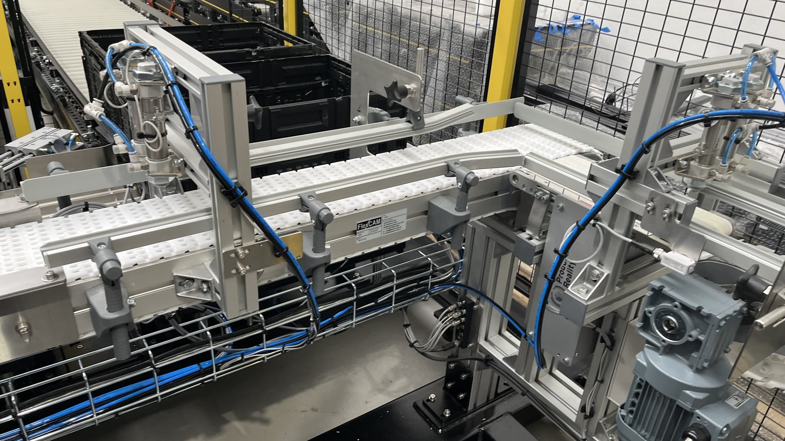
Food production
Robotic food-packaging cell
Robot-assisted product handling with conveyors, custom gripping equipment and a guarded cell. The mechanical layout brings product transfer, robot access and the surrounding equipment together.
- Robotic handling
- Conveyor transfers
- Custom grippers
Selected work
CAD, tooling and finished parts
Product & tooling development
Moulded tray system and injection mould
The same design through mould engineering, CNC machining and the assembled moulded parts.
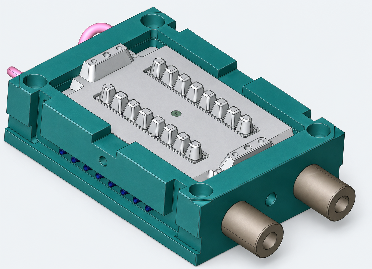
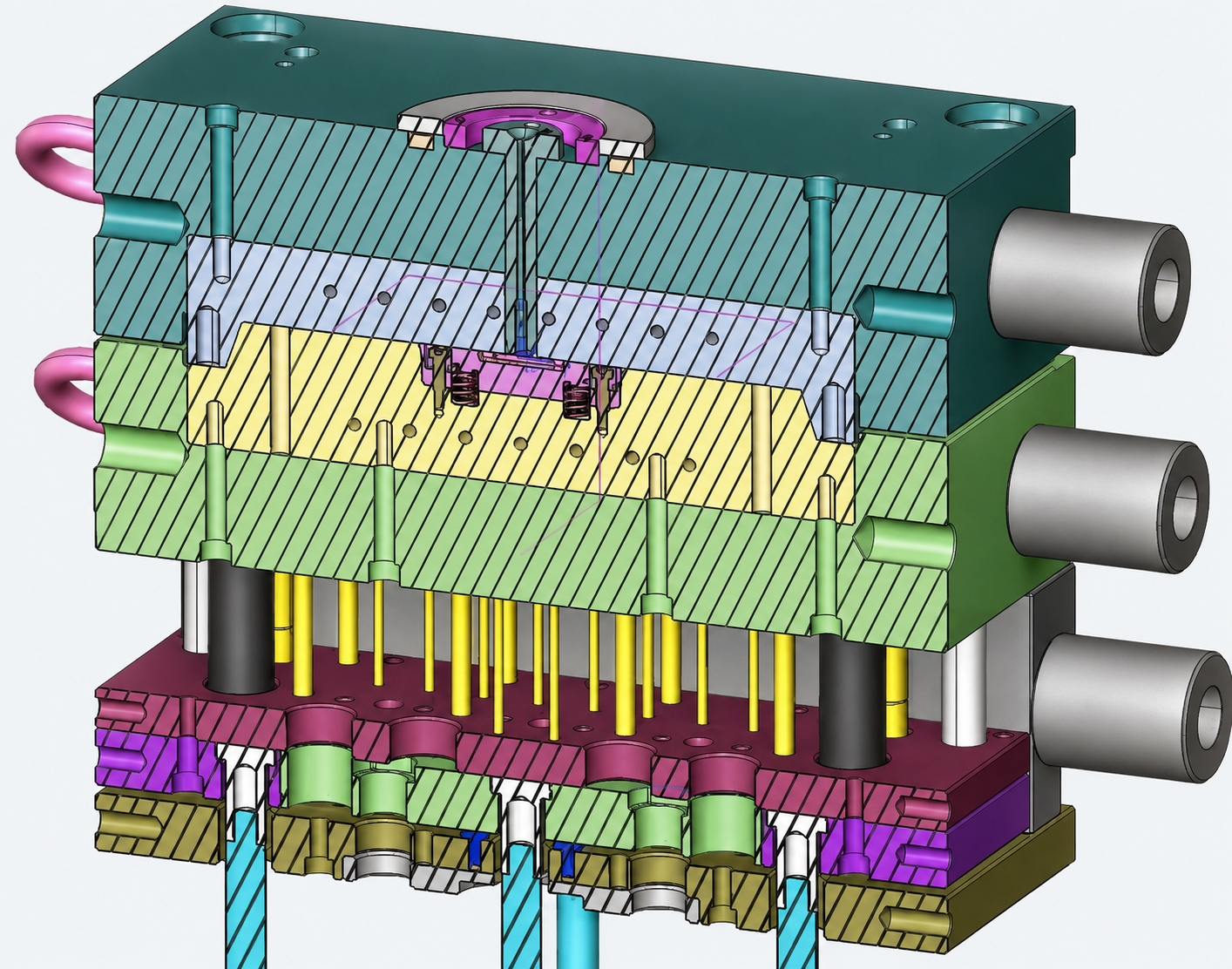
01 / Tool design Mould design and cross-section
The mould layout and its internal construction.
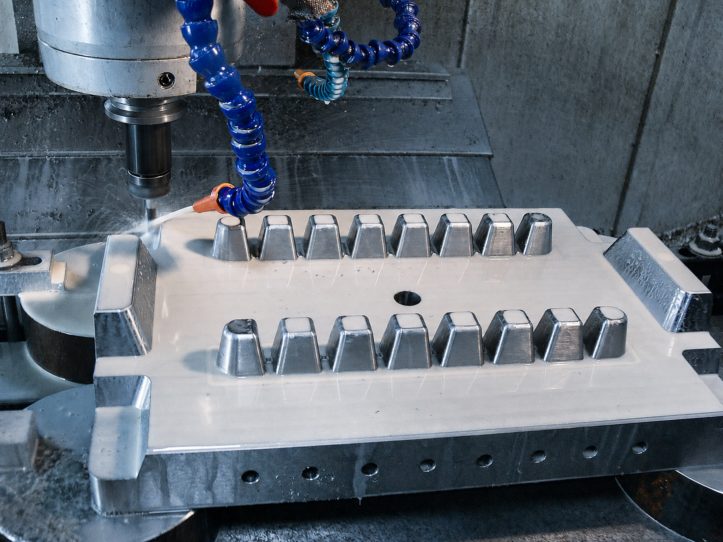
02 / CNC machining CNC-machined mould insert
Machining the mould insert shown in the CAD model.
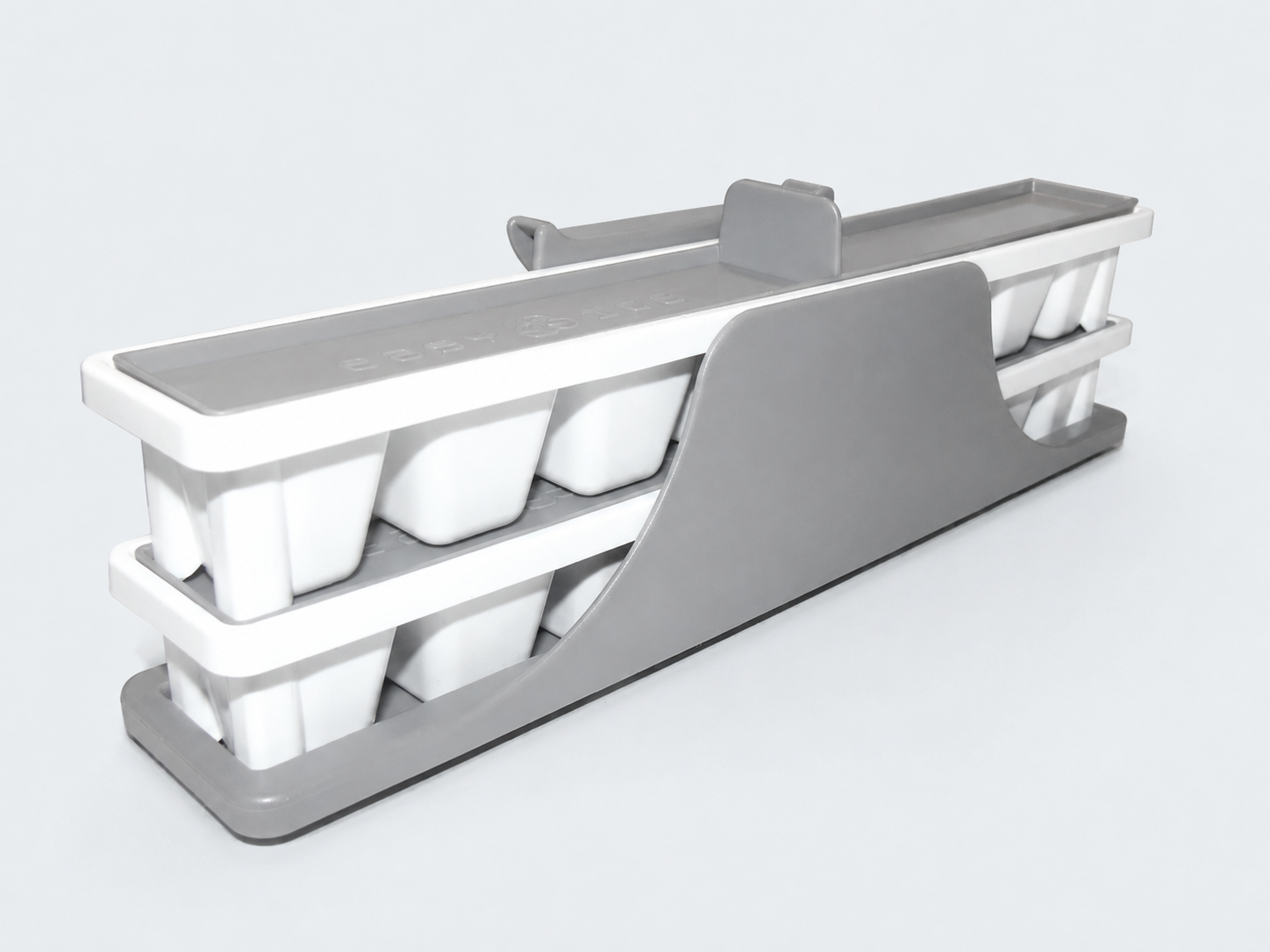
03 / Moulded assembly Finished trays and support cradle
The trays and cradle as a working assembly.
Mechanical assembly
Picatinny scope mount
A Picatinny scope mount for an assault rifle, shown as an assembly model and manufactured parts. The photographs show the rail, scope rings and mounting hardware.
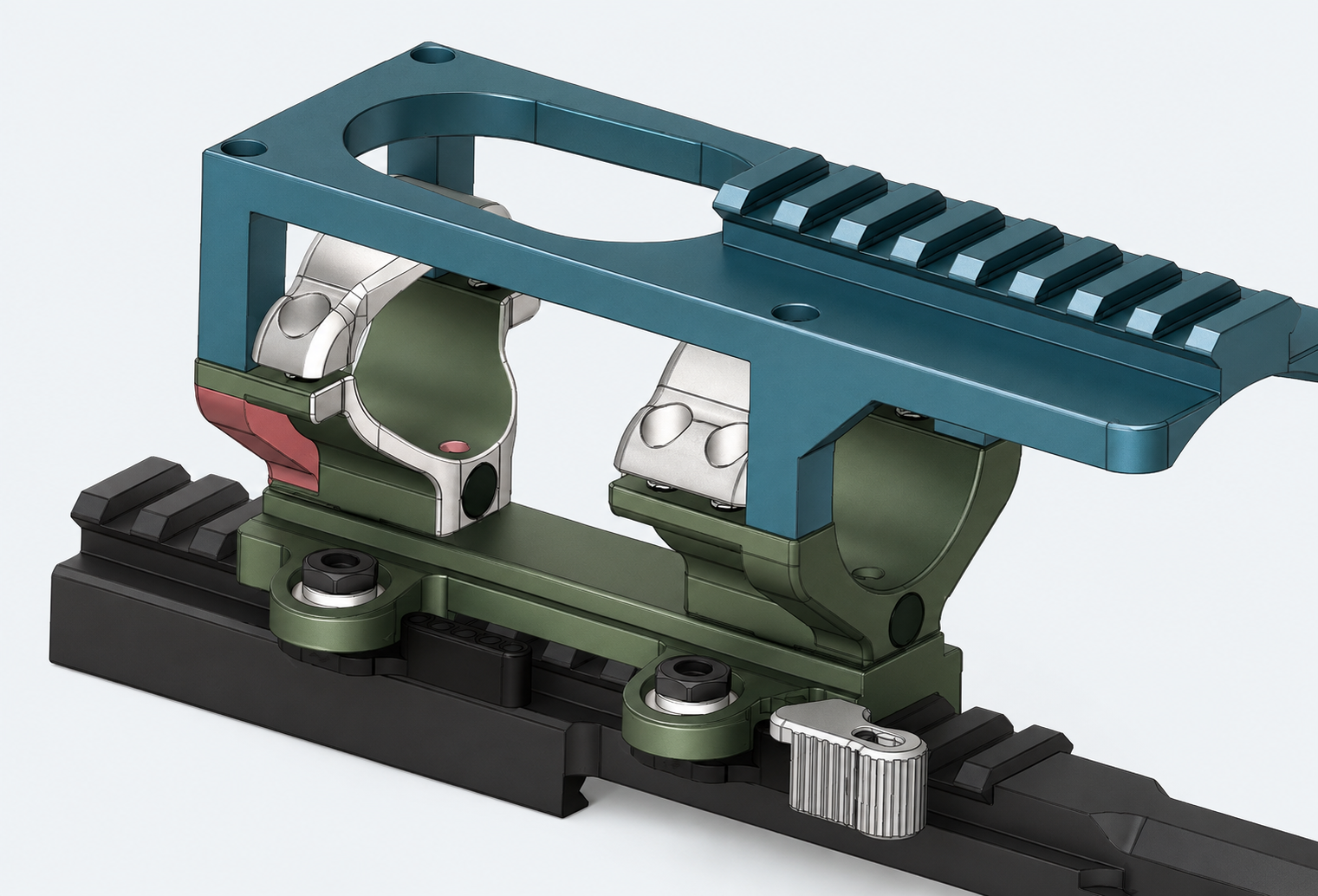
01 / Assembly CAD Scope mount CAD assembly
The rail, scope rings and upper bracket in the assembly model.
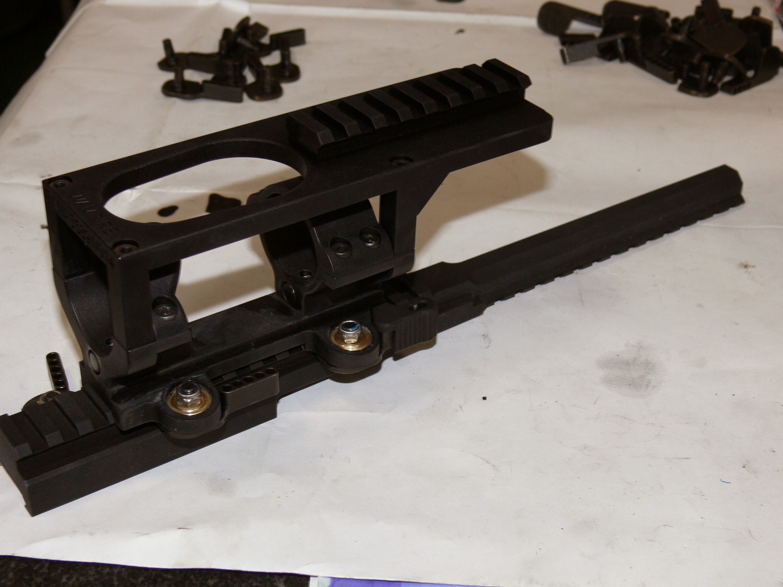
02 / Physical assembly Manufactured scope mount
The scope rings and bracket assembled on the rail.
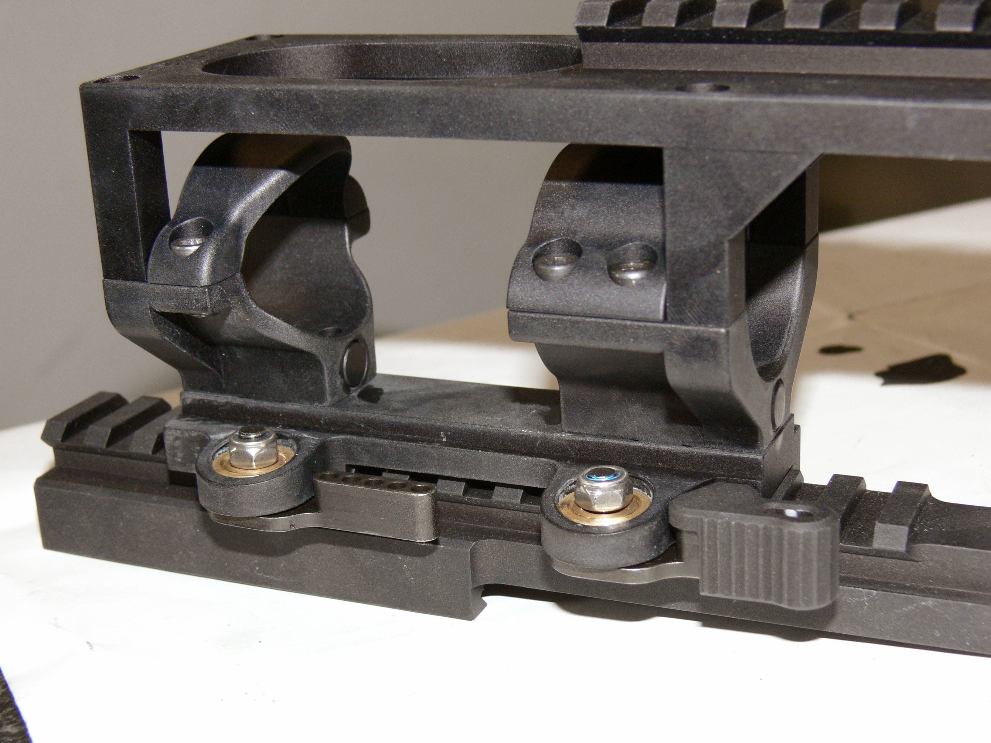
03 / Close-up Clamps and fasteners
Detail of the assembled clamps and mounting fasteners.
Machined assembly
Sensor gimbal assembly
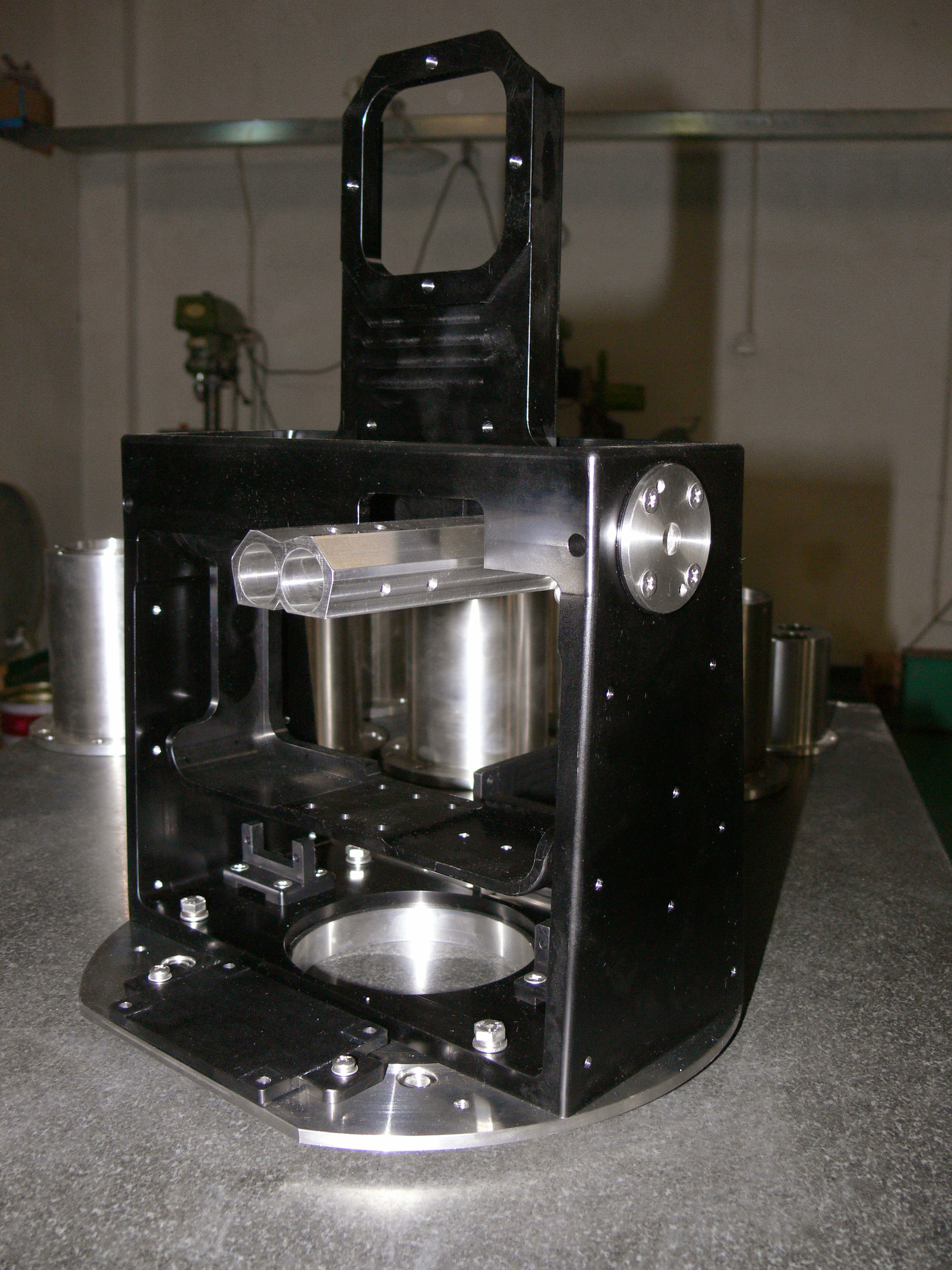
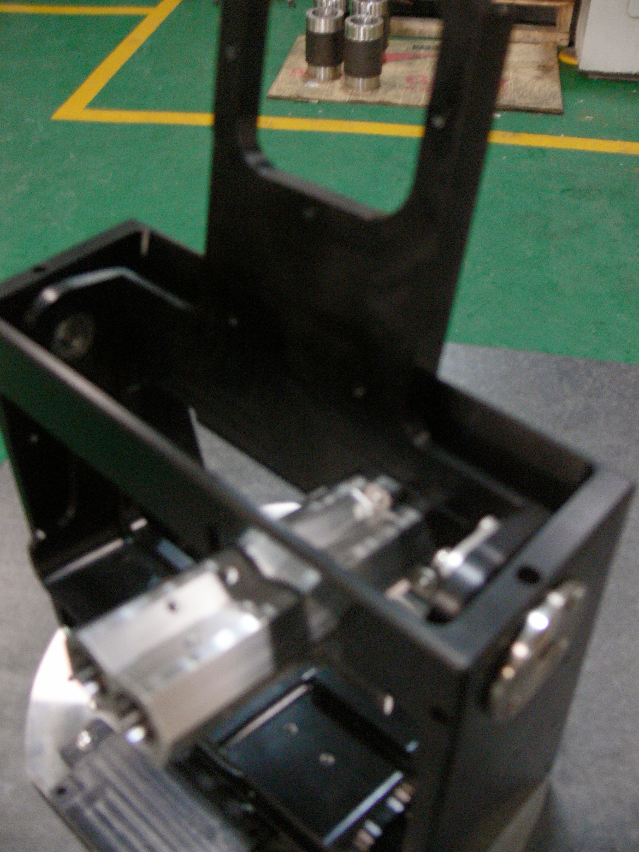
A machined gimbal frame with a circular base and internal supports. Potential applications include positioning radar or vision sensors for industrial and defence equipment; the photographs show the mechanical assembly.
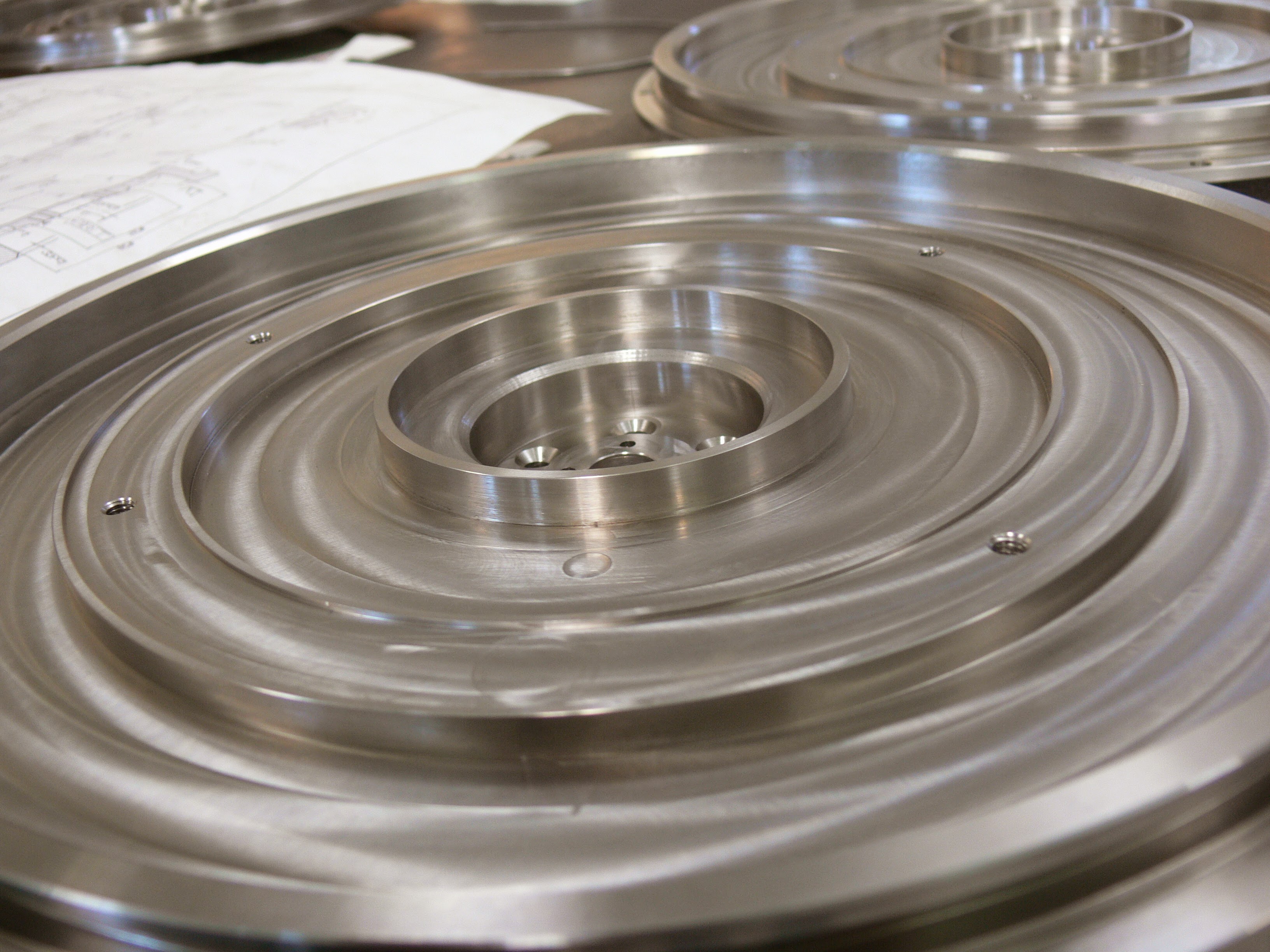
Machined circular plates
Machined plates with stepped profiles and mounting features.
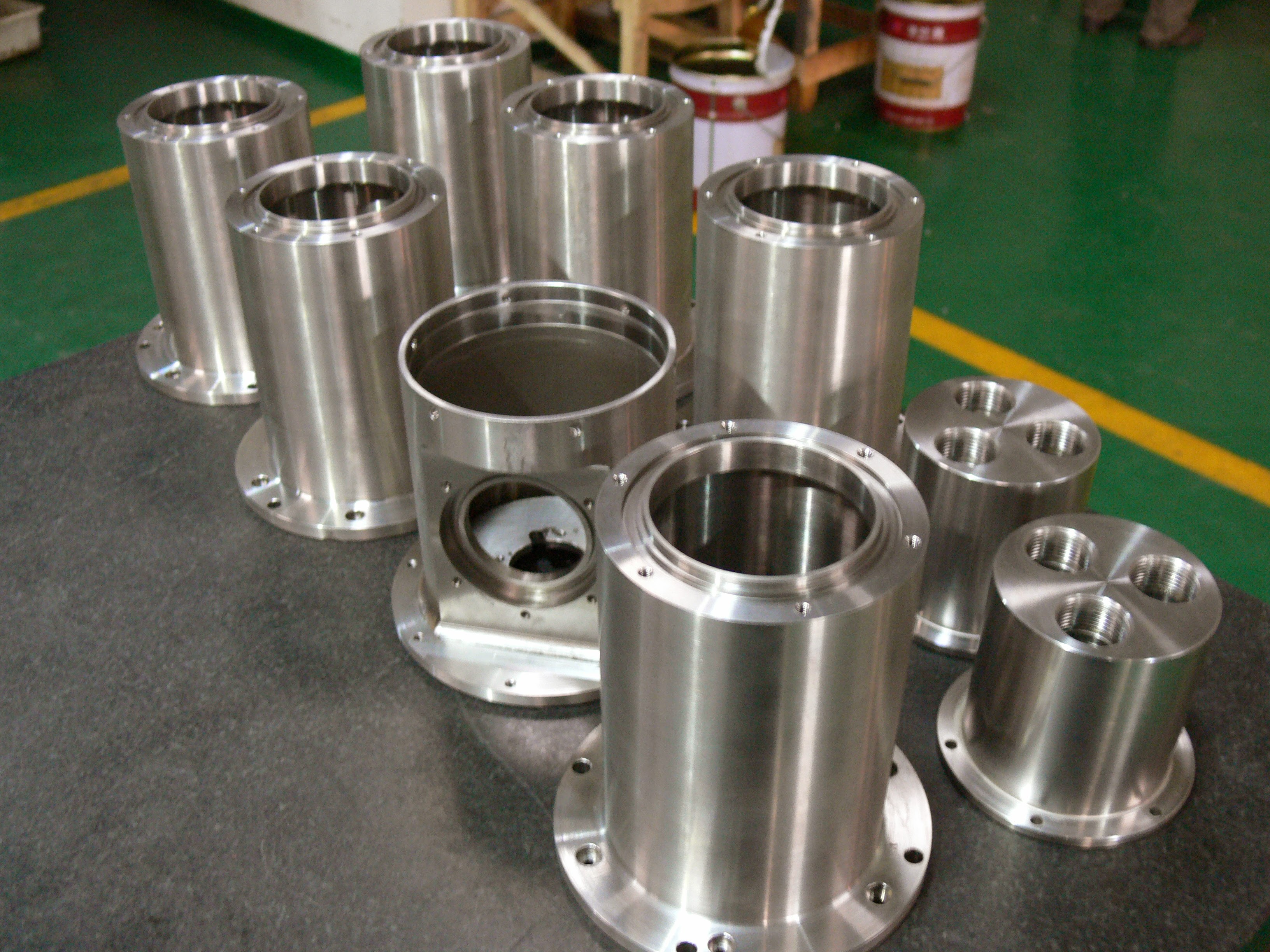
Machined housings and flanges
Cylindrical parts with internal features, flanges and threaded connections.
Tooling documentation
and export packing
Completed tooling, protective wrapping, mould books and export crates.
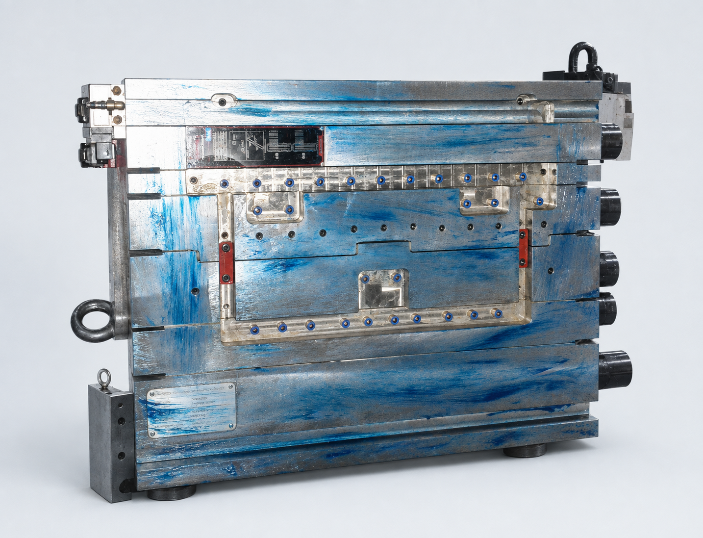
01 / The finished tool
Completed injection mould
The completed mould, showing the machined plates, connections and external hardware.
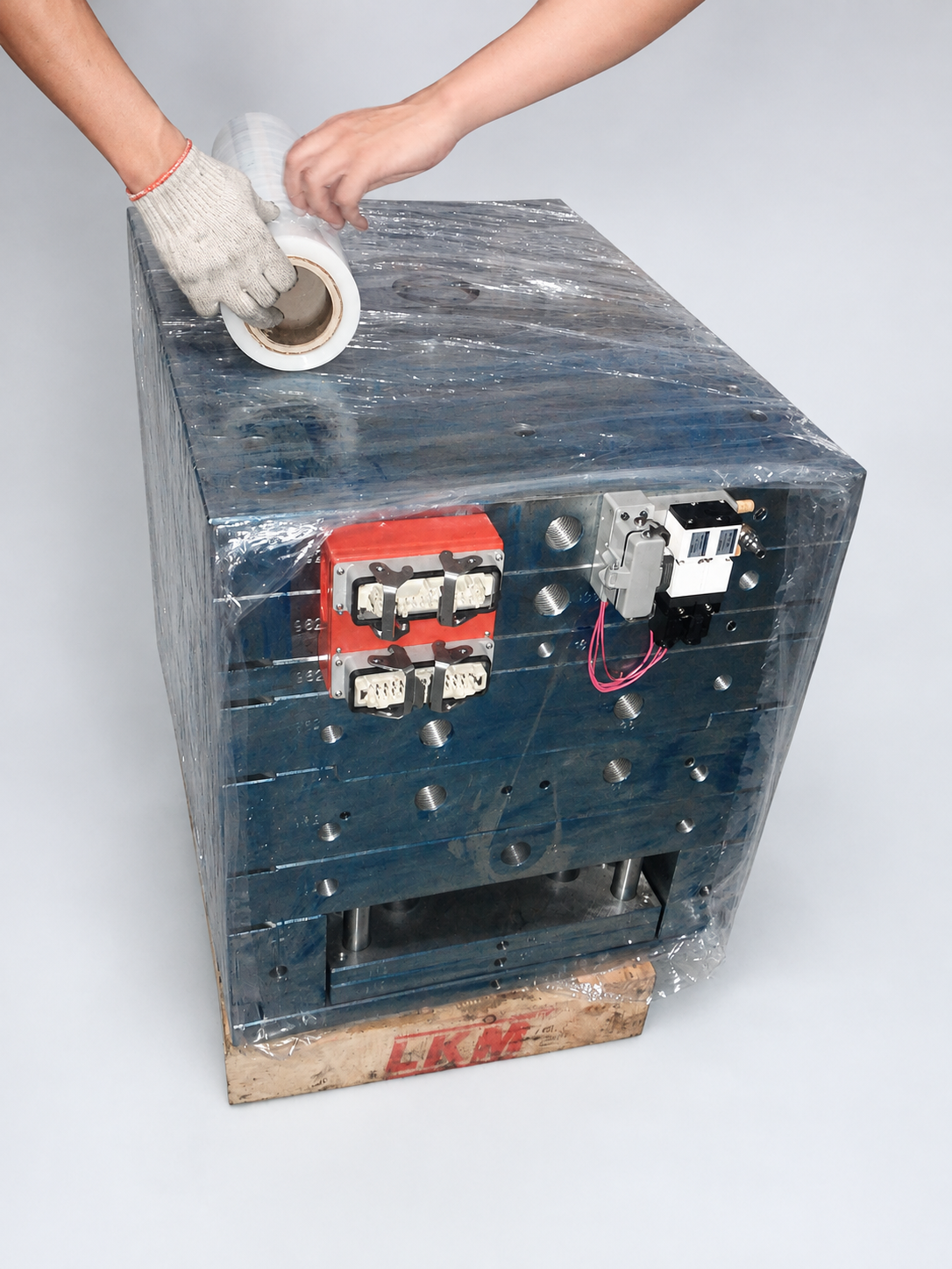
02 / Protection
Protective wrapping
Protective wrapping covers the tool before packing, with care around the external components.
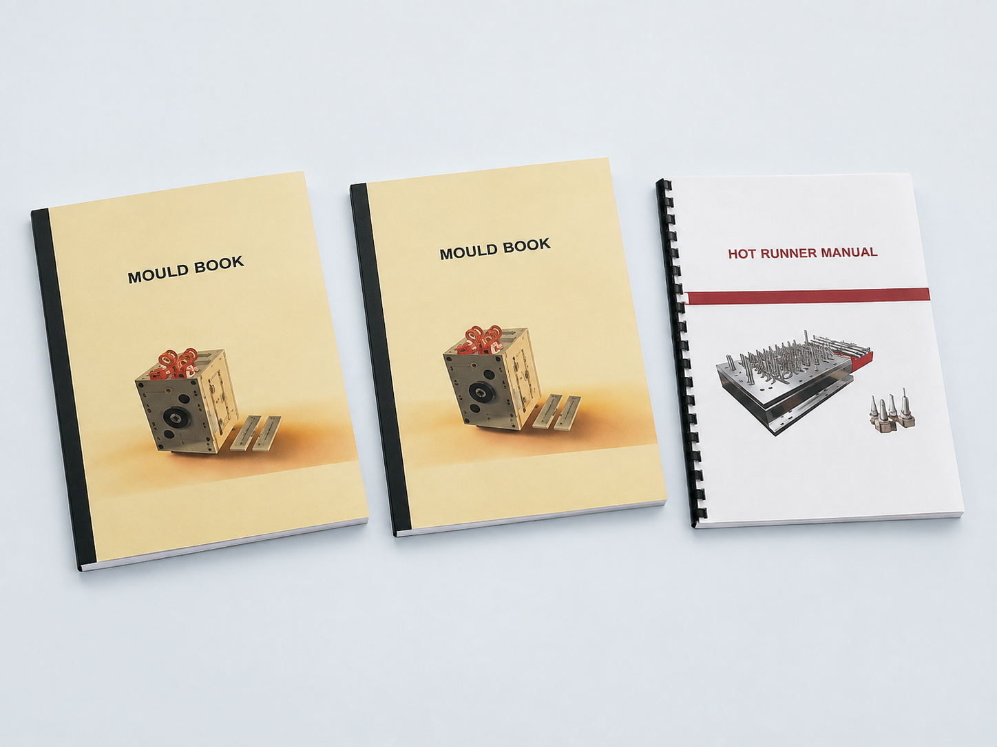
03 / Documentation
Mould books and manuals
The mould book and hot-runner manual accompany the hardware, giving the receiving team a practical reference.
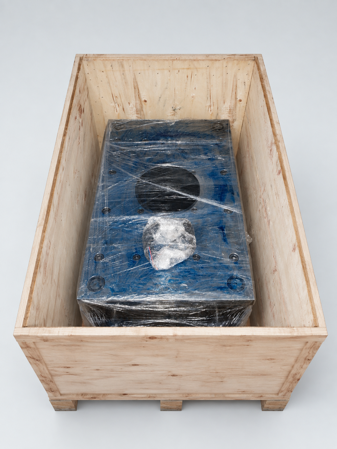
04 / Export packing
Wooden export crate
The wrapped tool is packed in a wooden crate for export.
More selected work
Production tooling reviews
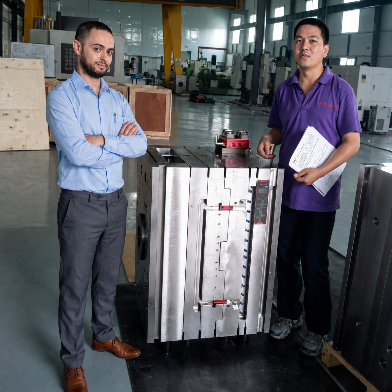
Tooling & production readiness
Injection mould tooling and trials
Tool design reviews, mould trials, part inspection and production release.
Tool reviewT0–T2 supportInspectionIssue closureRelease
Production support